In this article I will talk through creation of a remote controlled robot buggy.
Needless to say, there are plenty of articles and videos on how to do this already utilizing a multitude of approaches. In this article, I will talk through the approach I used, issues I ran into along the way, how I fixed them. The goal is to provide answers on why certain strategies work in some cases and not others.

What you will need
- A Raspberry Pi – I used a 3A + for this one
- A motor control driver – I used a Qunqi L298N Motor Drive Controller Board Module Dual H Bridge DC Stepper which I purchased on Amazon
- An appropriate Chassis with at least Motors and wheels – I purchased the cheapest one I could find online with 2 motors
- A phone power bank which can provide – 5V and 2amps with an appropriate mAh. I used a 5000 mAh one I had lying around at home
- 4 AA batteries and a battery holder
- A wireless keyboard to serve as the remote control.
- Wires and Jumper cables
- Access to a decent soldering iron. (we will be doing some basic soldering )

The Raspberry Pi
The key thing here is the Raspberry Pi – this will be the brains of the operation and it’s compute power will determine how smart the robot can be.
I evaluated both my Raspberry Pi 3B + as well as the 3A +. The limiting power was the power consumption of the devices. With a fully loaded Pi 3B+ with a wireless keyboard attached to the USB and WiFi running seemed to get really hot in about 5-10 minutes. Also, my power source seemed to have trouble keeping up with the power requirements with the Pi repeated restarting due to running out of power.
The 3A+ has just a bit less power consumption and – with BlueTooth, WIFI, VNC and SSH all turned off and just a wireless keyboard connected – seems to be doing a better job with my 5V & 2Amp power source. The downside is that it has a lower memory.
I’d really like to grab a Pi Zero or Zero-W and see the performance but as of now I’m sticking to the Pi 3A+
Power Source
This was my first remote project so I wasn’t sure what power source to use. For a remotely powered Pi, you really need to worry about both the power source as well as the power cord (I used a USB to mini-USB) connecting the power source to the Pi.
For the power source – I experimented with a couple of phone power banks which were lying around the house. I initially tried to use a cheap 5V 1Amp one but found that it was unable to hold a steady enough current to my Pi 3B+. The red LED on the Pi kept shorting in and out indicating the power was coming on and off and eventually corrupted my SD card.
I found another one with 5V and 2 Amps (which I believe is the highest you can do without damaging the Pi) and got a steady red light.
The power cable matters as well. I had a bunch of USB to mini-USB cables lying around at home but found that, with some, even when I was plugged into the wall socket, I wasn’t able to maintain a steady power to the Pi. I eventually found a wire I liked to go with my power bank and have been able to run things flawlessly since then.
I did look at configuring my own UPS power source using a Lithium battery and a board. I believe using a good UPS will make the power cord less critical.

I’ve learnt the hard way that no red LED is better than a flickering red LED. A red Light coming on and off means the SD card is eventually going to be corrupted
Currently, I am using a Pi3A+ with all non-essential programs off including WiFi, Bluetooth. I have VNC and SSH off as well so if I need to troubleshoot the code/settings I need to connect the Pi to a Monitor via HDMI
Controlling the PI Remotely
I had to choose a way to control the buggy remotely. VNC would need the buggy to be tethered to a WiFi and I wanted to be able to take it around.
The other options I had were
- Connect to it via Bluetooth and use an App like BlueDot
- Use my wireless keyboard.
I went with the latter.
Wiring everything up
I grabbed the cheapest chassis I could find on Amazon. I found one for $11 which came with 2 motors and a battery holder for 4 AA batteries.

Your Drive Controller is the key here – you essentially wire everything up to it. The layout will vary for each controller but essentially;
A) Connect the Motors to the DRIVER
On an L298N, there should be 4 terminal blocks used for the motors (numbered 1-4) in the diagram above.
That’s 2 per motor. It is ABSOLUTELY ESSENTIAL that the jumper cables be soldered onto the motors or you end up getting a loose connection.
I’m no expert on soldering, but it is a bit like painting in that if you do a poor job you can get something workable by applying another coat. I actually did a poor job initially and had a wire pop out after I assembled the robot. Not too much of a problem though, I just tipped the assembled robot over and redid it

B) Wire the Battery Pack to the Power Side
There should be 3 more terminal blocks. You are looking to identify the ones marked VCC and GND. (marked 5 & 6 in the diagram above). Number 7 is a 5V output block which gives you the option of powering the Pi via the controller.
Essentially, the black wire (negative), from the battery pack goes to the GND and the red one (positive) to VCC.
I used 4 standard AA batteries which meant I was powering my buggy with 6V. the L298N can support up to 35V. I do intent to amp up the power in the future to see how much I can push it. However, with the current power I was able to also mount my 7in touch screen which weighs close to a pound without issue. I’m fairly confident I can pop on some more hardware onto the setup without issue.
C) Connecting to the Pi
The final step is connecting the Driver to the Pi. This requires connecting the GPIO Pins on the Driver to the Pins on the Pi.
There are 4 female GPIO Pins on the Driver. I’m told, if you look closely you will see them labeled INT1-4.
You need to connect them to GPIO pins on your Pi. I chose 17,22, 23 & 24. These can be anything but will be referenced in the Code we write.
You also have to run a jumper from the GND terminal block to one of the Ground Pins on the Pi.
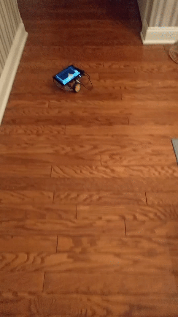
The finished product looked something like the below.

Developing on the Pi
With the wiring set up, we have everything we need to have the Pi control the buggy.
…except for the code which we will write below.
Before we go further, it is worth noting that I am running Raspbian version 9 (Stretch) . I mention this because, the behavior of things like autostart files and config files do vary based on OS and version. To check the version of Raspbian simply use this command:
cat /etc/os-release
Controlling the Robot
The code to control the robot involves using the GPIOZERO library. You essentially import Robot from GPIOZERO and use the commands to move the robot around.
In addition, I used curses and getch() to capture keystrokes on my keyboard and then map the keybinds to the forward(), backward(), left() and rigth() functions of Robot
I will not get into took much detail here since this functionality is well documented elsewhere on the internet. The code below is what I finally used and is a mishmash of what I saw on other sites.
For a great explanation of this check out this link: https://www.youtube.com/watch?v=j6mglfhWZrQ
from gpiozero import Robot
from time import sleep
import os
import curses

robby = Robot(left = (22,17), right=(23,24))
print('robby initialized')

robby.forward(.9)
sleep(1)
robby.stop()

screen = curses.initscr()

curses.noecho()
curses.cbreak()
curses.halfdelay(3)

screen.keypad(True)

try:
    while True:

        char = screen.getch()
        #primt char
        if char == ord('q'):
            break
        if char == ord('p'):
            curses.nocbreak()
            screen.keypad(0)
            curses.echo()
            curses.endwin()
            os.system('sudo halt')
        elif char == curses.KEY_UP:
            robby.forward(.9)
        elif char == curses.KEY_DOWN:
            robby.backward(0.6)
        elif char == curses.KEY_LEFT:
            robby.left(.7)
        elif char == curses.KEY_DOWN:
            robby.right(0.7)
        else:
            robby.stop()

finally:
    curses.nocbreak()
    screen.keypad(0)
    curses.echo()
    curses.endwin()
Note: pressing p allows me to shut down the Pi . This is important because I did not plan to attach a UI to the buggy and the button would let me shutdown the system gracefully without corrupting my SD Card. (you cannot just pull out the plug)
HOWEVER… once you press the p button, you need to WAIT a while before you can actually pull the plug. During the shutdown, the GREEN led (next the the all important red led) will blink a number of times indicating IO operations in progress. Only after the blinking stops and the led goes off completely can you unplug the Pi. This is very important to preserve your SD Card
The above code needs a terminal to run successfully. If you are already in a terminal, you can launch it simply by entering:
python3 PATH-TO-CODE/filename.py
If you are not in a terminal however, you need to make sure your script opens one. You can do this by creating a Bash script like this to open a terminal and launch the Code;
#!/bin/bash
export TERM=linux
export TERMINFO=/etc/terminfo
python3 SCRIPT-NAME.py
make this executable using;
chmod +x NAME-OF-FILE-CREATED-ABOVE.sh
and you are good to go. You can now invoke the above code from anywhere and, regardless of where you are, you have a robot which responds to your direction keys.
Final thoughts
This was my first Pi project where I ran something remotely.
By far, the most challenging factor to the robot was the power source to the Pi. I had to experiment with various combinations of Power cord and Battery pack to find something that I felt confident in. I haven’t really pushed the system but have been able to run the buggy for about half an hour with the current setup without too much deterioration in the battery level.
I plan to add some more bells and whistles to the project which will likely make the Pi a bit more power hungry so I might revisit the power supply situation
I did play around with a couple of options where I could launch my code on startup of the Pi and using keybinds. The initial goal was to do away with the UI altogether. While they work, they seem to be dependent on the version of the OS and it looks like an update can blow it away at any time. I was more comfortable attaching a small UI (I have a 3.5 inch screen which connects to the Pi via HDMI) to start it up, unplug it to run and then shut down the robot with the keybind in my code.
I plan to revisit this project in the future when I have more time and will likely have an update when that happens.
